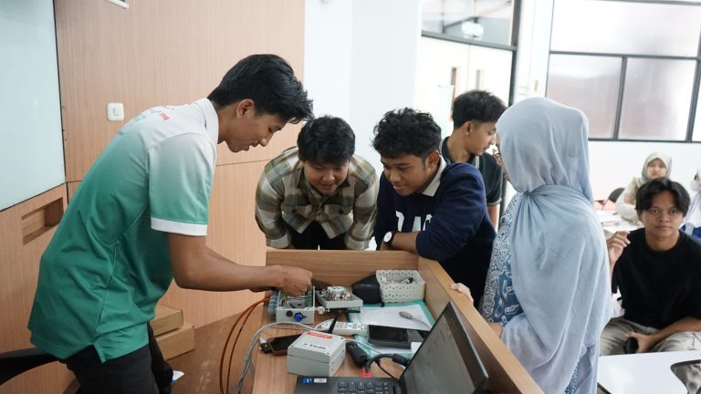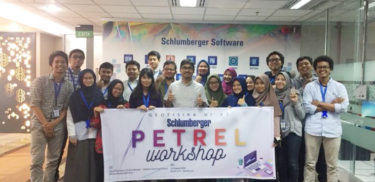
The HMGF UI (University of Indonesia) held a Schlumberger Petrel Workshop, initiated by the HMGF UI 2018 division of the Professional Affairs Department, at the Sapphire Room (Schlumberger – Jakarta Learning Center), Wisma Mulia, South Jakarta, on Thursday, August 23, 2018.
The workshop, which began at 9:00 a.m. and concluded at 4:00 p.m., was attended by 20 HMGF UI students from the classes of 2014 to 2017. Ian Arthur Kainama, the workshop instructor, led and explained the material on Schlumberger’s Petrel software.
Petrel is widely used software in the petroleum exploration and production industry. First developed in 1996, the software can be used to interpret seismic data, create reservoir models, calculate volumes, create maps and designs to maximize reservoir exploitation, and more (2002, itredaktor.com).
The agenda of this workshop broadly consists of 4 main points, namely discussions regarding Seismic Well Tie, Seismic Interpretation & Mapping, Seismic Attributes: Volume and Surface, Velocity Modeling & Data Conversion.
Seismic Well Tie
Seismic Well Tie In Indonesian, it can be interpreted as the process of tying well data to seismic data. Seismic Well Tie is divided into three main stages, namely Preconditioning Data, Sonic Calibration, and Synthetic Generation.
Checkshot Data very important to produce Synthetic Seismogram, produces data on the relationship between time and depth, and in the process QC (Quality Control) must be continuously carried out on checkshot data sebelum data diimport dan diproses lebih lanjut.
after stage Preconditioning Data, selanjutnya dilakukan Sonic Calibration The main objective of which is to match seismic data (checkshot) in time and integrate sonic time data at each depth point in the well. The final stage of this first process is Synthetic Generation as a bridge between the geological information that has been obtained (well data in depth (m)) with geophysical data (seismic data in time (s)).
This stage will produce good time and depth relationship data and can facilitate interpretation in determining the seismic response to the lithology and fluids in the well being studied.
Seismic Interpretation & Mapping
The second stage will produce an interpretation of the subsurface horizon of the earth which requires various techniques, namely Manual Interpretation, Guide Autotracking, Seeded 2d Autotracking, Seeded 3d Autotracking, Autotrack inside polygon, Active box autotracking, paintbrush autotracking, and interpolate inside polygon.
Seismic Attributes: Volume and Surface
The attributes in question are calculated data derived from seismic data. Seismic attributes are used to aid interpretation processes at various scales, from analyzing regional depositional systems to detailed mapping of structures, stratigraphy, and rock properties.
In this workshop, the various attributes required to create a surface were utilized optimally, resulting in a surface model.
Velocity Modeling & Data Conversion
At this final stage, all participants can understand various ways to:
- create and edit surfaces from seismic horizon,
- create a velocity model an perform domain conversion,
- definy velocity model intervals,
- create a velocity model intervals,
- create a velocity model with uncertainty,
- perform a depth conversion using the active velocity model,
- perform a general depth conversion.